MECH 3652, Machine Design
Lightweight Cantilever Support Structure
A welded A36 I-beam frame optimized to carry a 1000 N offset load at 2.96 kg, verified for fatigue, buckling, weld strength, and anchorage.
2.964 kg
Final weight
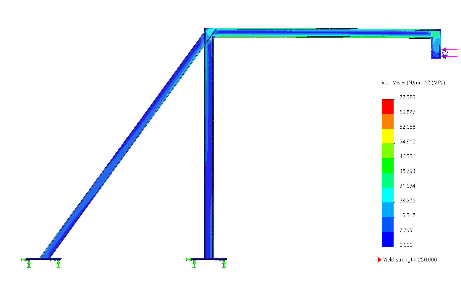
77.6 MPa
Peak stress
3.80 mm
Max deflection
3.22 (req. 2.0)
Factor of safety
6.2M cycles (req. 10k)
Predicted fatigue life
Overview
A floor-mounted steel structure carrying a 1000 N horizontal load applied 500 mm from the floor without touching the adjacent wall. Five concepts were screened in a weighted matrix, then the selected frame was optimized through a cross-section study, topology study, and a seven-step mesh convergence to 3.06 million elements. The final four-member I-beam design weighs 2.964 kg with 77.6 MPa peak stress, 3.80 mm deflection, and FOS 3.22, with welds, anchor bolts, Euler buckling, and Marin-Goodman fatigue all verified for 10,000 cycles at 99 percent reliability.
Problem
The structure must resist a 1000 N horizontal load applied 500 mm above the floor and 500 mm out from a wall it is prohibited from touching, fixed only to the top surface of the floor. The design is limited to ASTM A36 steel and must hold a minimum factor of safety of 2.0 with 99 percent reliability over 10,000 load cycles.
The load path puts the frame in combined bending, shear, and axial action with buckling potential, so the central tradeoff is strength and rigidity against mass. The objective was the lightest structure that still meets every failure-mode check.
Concept Selection
Each of the five team members modelled and FEA-tested an independent concept. My concept was a three-beam inverted-V frame: 59.8 MPa, 2.11 mm, 1.67 kg, FOS 4.18, the lightest and safest of the five, but its 3D weld geometry scored poorly on manufacturability.
A weighted decision matrix (deflection 30%, manufacturability 30%, mass 20%, FOS 20%) selected a three-member planar frame at 7.8 of 10. It scored a 10 on manufacturability: every member lies in one plane, so it can be cut and welded from standard sections with simple fixturing.
Cross-Section Optimization
Three cross-sections were compared at near-constant structure weight so stiffness, not added material, decided the result. The hollow square baseline gave 81.8 MPa and 5.45 mm at 2.984 kg. A hollow circle was worse on both counts (96.1 MPa, 7.47 mm). The I-beam won decisively: 77.6 MPa, 3.80 mm, FOS 3.22 at 2.964 kg.
Two I-beam profiles were sized: a 25.2 mm deep section with 20 x 2.5 mm flanges and 5 mm web for the diagonal, and a 22.45 mm deep section with 20 x 3 mm flanges for the remaining members.
Topology and Mesh Verification
I ran the topology study and the mesh convergence. The topology optimization, constrained to hold FOS 2.0 at minimum mass, proposed web and flange cutouts that were rejected as impractical to manufacture; the fact that it removed little else confirmed the frame was already near-optimal.
The convergence study refined the global mesh from 5 mm to 1 mm (40,939 to 3,056,413 elements), keeping at least three elements across the 5 mm webs and probing 1 mm away from the singular corner. Stress converged within 5 percent over three consecutive refinements at 126.7 MPa, the conservative value carried into the fatigue calculations.
Fixtures, Buckling, and Fatigue
Hand calculations closed every remaining failure mode. Fillet welds were sized per AWS minimum leg for 5 mm material with E60xx electrodes; weld shear works out to under 1 MPa against a 124 MPa allowable (static FOS above 130, fatigue FOS above 70 using the 2.7 end-of-weld concentration factor with shear Goodman).
The frame anchors through welded A36 base plates and four 0.50 in F1554 Grade 36 concrete anchor bolts, each loaded below 0.7 MPa against a 36.6 kN tensile capacity. An Euler check on the compressed horizontal member gave a 24.3 kN critical load against 0.77 kN applied.
Member fatigue used the Marin equation (surface, size, load, and 99 percent reliability factors) for an endurance limit near 104 MPa, then the Goodman criterion on the converged FEA stress. The 10,000-cycle fatigue strength is 237.9 MPa against the 126.7 MPa applied, and the predicted life is 6.2 million cycles. A SolidWorks fatigue study on the converged model showed no damage at 10,000 cycles.
Outcome
The recommended design is a four-member welded I-beam frame at 2.964 kg that exceeds every requirement: FOS 3.22 against the required 2.0, deflection held to 3.80 mm, welds and anchorage with large margins, no buckling risk, and fatigue life three orders of magnitude past the requirement.
The discipline of the project was closing the loop between methods: FEA results were only trusted after convergence, analytical checks used the converged values, and the topology study validated rather than redrew the geometry.
Image Gallery
Additional renders, drawings, and analysis outputs from the project.
Next project
4:1 Tractor Speed Reducer