MECH 3892, Mechanical Laboratories in Solid Mechanics
Ground Rover Structural Redesign
An analytical, FEA, and experimental redesign of a four-wheel rover chassis and wheels that lightens the structure and nearly doubles obstacle clearance.
3.75 in (was 2.25)
Max obstacle cleared
0.042 in
Deflection at 7 lbf
0.1 in
Deflection limit
2.19 lbf
Max towing force
4 in (was 3)
Wheel diameter
Overview
A Phase 2 structural redesign of a prototype four-wheel ground rover with an HDF body, PLA wheels, and four 24 V motors. Hand calculations, SolidWorks FEA with mesh convergence, and static, aggregate, and obstacle testing validated two changes: chassis lightening holes and larger 4 in paddle wheels. The rover stayed well under the 0.1 in deflection limit at 7 lbf (0.042 in), dropped weight, and raised obstacle clearance from 2.25 to 3.75 in.
Problem
The prototype is a four-wheel ground rover with a high-density fiberboard (HDF) body and four 24 V motors paired per side for skid steering. Phase 1 found it could carry the static load and cross gravel, but it could not climb obstacles taller than 0.75 in on a head-on approach.
Phase 2 set out to improve climbing and reduce weight without losing strength or exceeding the 0.1 in chassis deflection limit at a 7 lbf payload.
Approach
Three methods cross-checked every decision. Analytical models reduced each component, chassis, rocker, motor mount, and wheel paddles, to beam-bending cases to estimate stress, deflection, and moment of inertia, treating the materials as linear-elastic and isotropic under static load.
SolidWorks FEA then localized stress and displacement, with a mesh-convergence study on each part holding stress change under 5 percent and symmetry models to cut computation. St. Venant's principle was used to discount sharp-corner stress artifacts the solver cannot resolve.
Experimental tests rounded out the static models: a static load test with a threaded rod, load cell, and caliper; an aggregate pulling-force test on 0.15 in gravel; and an obstacle-climb test on stacked blocks.
Design Changes & FEA
Two changes drove Phase 2. Lightening holes were cut into low-stress regions of the chassis to shed mass without losing stiffness; FEA put chassis deflection at 9.56e-4 in and stress at 0.179 ksi, confirming the structure was stiffer than the load required. The wheels were enlarged to 4 in diameter with every other paddle extended outward for climbing and traction.
The wheel paddles were checked in two load cases. Peak FEA stresses were sharp-corner artifacts; probe values of 0.39 and 2.11 ksi sat in the same order as the analytical estimates and below the HDF yield strength, giving confidence to move to physical testing.
Testing Results
Static load: vertical deflection was 0.042 in at 7.01 lbf, well under the 0.1 in limit, and 0.059 in at 9.82 lbf, still within limit, with no cracking or permanent deformation.
Obstacle climb: the rover cleared 2.25 in at both 0 and 45 degree approaches, where Phase 1 had failed the 2.25 in head-on case, and cleared 3.75 in at 45 degrees, a 1.5 in improvement.
Aggregate: pulling forces ranged from 0.60 to 2.19 lbf. The aggressive paddles dug into the gravel and lifted the front of the rover, shifting weight onto the rear wheels and pointing to a center-of-mass correction.
Outcome & Key Learnings
Phase 2 met its goals: a lighter chassis, obstacle clearance up to 3.75 in, and deflection held under limit. The three methods reinforced each other, analytical bounding the problem, FEA localizing stress and deflection with judgment on artifacts, and testing exposing the dynamic front-lift behavior the static models could not predict.
The clearest lesson was that static analysis alone misses real terrain behavior: the traction gain from the new paddles created a weight-transfer problem only the experiment revealed. Next steps are to rebalance the center of mass and evaluate a rocker-bogie suspension.
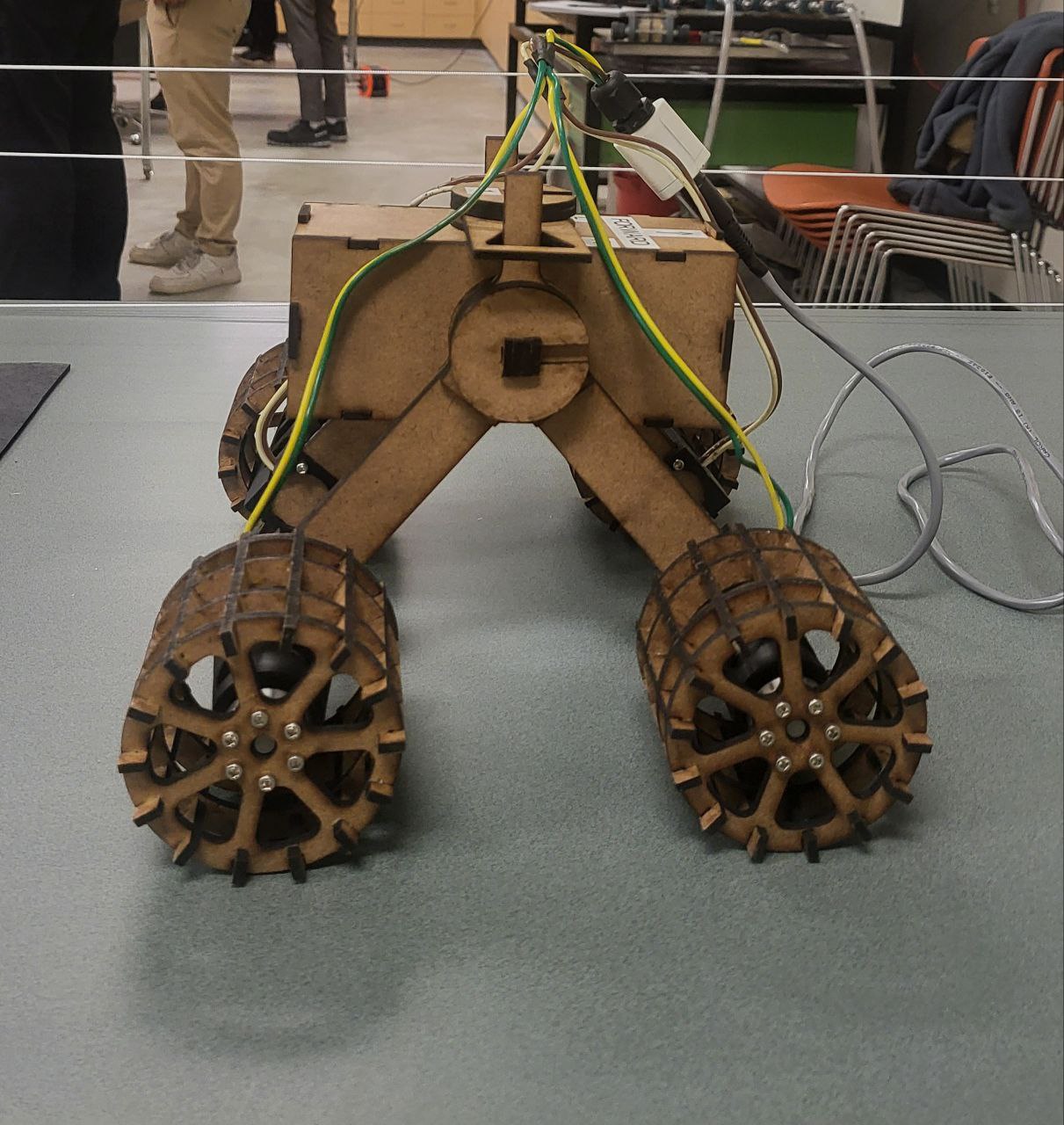
Image Gallery
Additional renders, drawings, and analysis outputs from the project.
Next project
Lightweight Cantilever Support Structure