MECH 3652, Machine Design
4:1 Tractor Speed Reducer
Chain, gear, and belt drives designed in full for a 60 hp tractor; the selected gear train and its output shaft sized for fatigue with bearings, keys, and retaining rings.
4:1 (two 2:1 stages)
Reduction
60 hp
Power
2670 N·m
Output torque
2.17 min
Shaft FOS
31.85 ksi converged
Shaft FEA stress
Overview
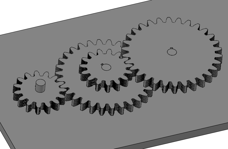
A 4:1 speed reducer carrying 60 hp from a diesel tractor engine at 640 RPM to a 160 RPM output at 2670 N·m. Complete chain, gear, and belt drives were designed and compared on transmission efficiency, contamination resistance, and packaging; the gear train won with two stacked 2:1 spur stages in AISI 4140, sized by AGMA bending and contact methods. The 42 in output shaft was designed end to end with Marin fatigue at four critical locations, iterating material from 1020 CR to 1050 CR steel to hold FOS above 2, and verified by FEA converged at 31.85 ksi.
Problem
The brief: design a speed reducer between 1.5:1 and 10:1 for 1 to 75 hp, with complete designs for a chain drive, gear drive, and belt drive, select one on engineering criteria, and fully design one of its shafts with bearings and retaining rings.
The chosen application is a tractor wheel drive: 60 hp in at 640 RPM, 160 RPM out, torque rising from 667.6 N·m at the input to 2670.3 N·m at the output. The drive operates outdoors in dirt, at low speed and high torque, with packaging on the tractor frame at a premium.
Drive Trade Study
All three drives were designed, not just compared on paper. The chain design used No. 100/120 single-strand roller chain with four sprockets and 15 in centers (about 44 in end to end); the belt design used two 2:1 V-belt stages with 9 and 18 in sheaves (43.5 in end to end, and a single-stage option would have needed a 36 in sheave); the gear design used four spur gears, two at 10 in and two at 20 in diameter (50 in tip to tip).
Selection weighed transmission efficiency, resistance to dust and debris, and installed size. Chain and gears beat the belt on efficiency and contamination; the gear train then won overall because it needs no tensioning or wrap-angle allowance, transmits torque tooth to tooth with no elongation or slip, and can be fully enclosed in a gearbox, which suits a machine that lives in dirt. Its slightly longer package was accepted as the cost of that robustness.
Gear Design
Each 2:1 stage pairs a 15-tooth, 10 in pitch-diameter pinion with a 30-tooth, 20 in gear, both 2 in face width at a 20 degree pressure angle in AISI 4140 Grade 1 steel (Sy 93 ksi, 197 HB). Sizing followed the AGMA method: Lewis form factor, dynamic factor Kv, geometry factor J, stress-cycle factors YN and ZN at 10^7 cycles, and through-hardened bending and contact strengths.
Tooth profiles were generated as DXF involutes and rebuilt in SolidWorks. Each gear carries a 1-9/16 in bore with a 3/8 x 1/2 in keyseat for torque transmission.
Output Shaft Design
The 42 in output shaft carries the final gear and drives both wheel hubs. Diameters at four critical locations (gear-seat shoulder, keyway edge, retaining-ring groove, bearing shoulder) were found iteratively: conservative first-pass stress concentrations from standard tables, a nominal diameter, then refined Kf and Kfs from notch sensitivity and the actual D/d and r/d ratios.
The first pass in 1020 CR steel held the shoulders (FOS 2.13) but failed the keyway at 1.63, so the material was stepped up to 1050 CR (Sy 580 MPa), bringing the keyway to 2.17. The retaining-ring groove initially screened at 1.61 using the worst-case Kt of 5.0; with measured groove geometry (0.068 x 0.047 in, 0.010 in radius) the true factors gave 2.61. The bearing seat was set at 1.1810 in to match a standard NTN 6406ZZ double-shielded ball bearing (8,800 RPM rating against 160 required), and keys were crush-checked to length: 0.472 in at the gear, 1.106 in at the wheel ends.
FEA Verification
Each gear stage was checked under its stage torque with the driven bore fixed, representing a jammed wheel as the worst case. Stage one peaked at 82.9 MPa and stage two at 133.7 MPa, both at the tooth contact patch with a secondary concentration at the keyseat corner, an order of magnitude below the 4140 yield and consistent with the AGMA sizing.
The shaft was meshed from 0.25 in down to 0.05 in elements (90k to 3.5M), converging within 1 percent over three refinements at 31.85 ksi near the gear edge, with 0.006 in total deflection under bearing supports and the full 1969.5 lb-ft output torque.
Outcome
The gear-driven reducer meets the 4:1 ratio at 60 hp with every component sized by hand calculation and confirmed by FEA: gears within AGMA bending and contact limits, and a shaft holding FOS above 2 at all four critical locations after one material iteration.
The shaft design was the core lesson: real factors of safety live in the details, keyways, ring grooves, and shoulder fillets, and the first material that survives the nominal sections is not necessarily the one that survives its own features.
Next project
End Effector Mount