Manitoba Hydro, GDD (issued for construction)
Proximity Probe Bracket (Installation)
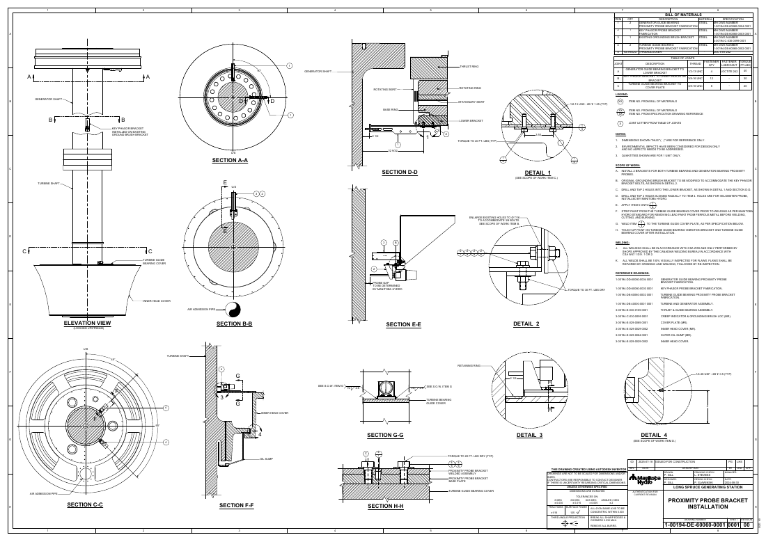
The installation drawing showing how the generator and turbine bearing proximity probe brackets mount onto the generator unit.
5 (2 turbine, 2 gen., 1 key-phasor)
Probe brackets installed
A0
Sheet size
40 ft-lb
Max joint torque
1-00194-DE-60060-0001
Drawing no.
P.Eng sealed, issued for construction
Release
Overview
An A0 installation drawing, drawn in Autodesk Inventor, that defines how the generator and turbine bearing proximity probe brackets and the key-phasor bracket are installed on the hydro generator unit, with sectioned assembly views and a joint torque table.
Bill of Materials
| Item | Qty | Description |
|---|---|---|
| 1 | 2 | Generator guide bearing proximity probe bracket (dwg 1-00194-DD-60060-0004) |
| 2 | 1 | Key phasor probe bracket (dwg 1-00194-DD-60060-0003) |
| 3 | 1 | Existing grounding brush bracket (modified) |
| 4 | 2 | Turbine guide bearing proximity probe bracket (dwg 1-00194-DE-60060-0002) |
| 5 | As req'd | Threadlocker, Loctite 242 |
Function
The drawing defines the installation of the proximity probe brackets on the generator unit. It locates the generator and turbine guide bearing probe brackets and the key-phasor bracket relative to the shaft, bearing covers, and existing hardware, using sectioned assembly views and details.
Installation Scope
Scope covers installing two brackets each for the turbine and generator bearing probes, modifying the existing grounding brush bracket to accept the key-phasor bracket bolts, drilling and tapping holes in the lower bracket, and adding velometer probe holes installed by Manitoba Hydro. The turbine bracket is welded to the guide bearing cover after lead-paint removal, followed by touch-up painting. The probe gap is set by Manitoba Hydro.
Joints & Standards
A joint table specifies each connection: generator guide bearing bracket to lower bracket (1/2-13 UNC, 4 fasteners, Loctite 242, 40 ft-lb), key-phasor bracket to creep-indicator bracket (3/8-16 UNC, 12 fasteners, 30 ft-lb), and turbine guide bearing bracket to cover plate (3/8-16 UNC, 8 fasteners, 20 ft-lb). Welding follows CSA W59 and W47.1 with 100 percent visual inspection. The drawing was sealed by a Professional Engineer and issued for construction.
Drawing Sheet
The full vector drawing with title block, views, and dimensions. Open in a new tab or download the PDF.
Next project
Automated Cone Inspection System