MECH 4860, Engineering Design Capstone
Automated Cone Inspection System
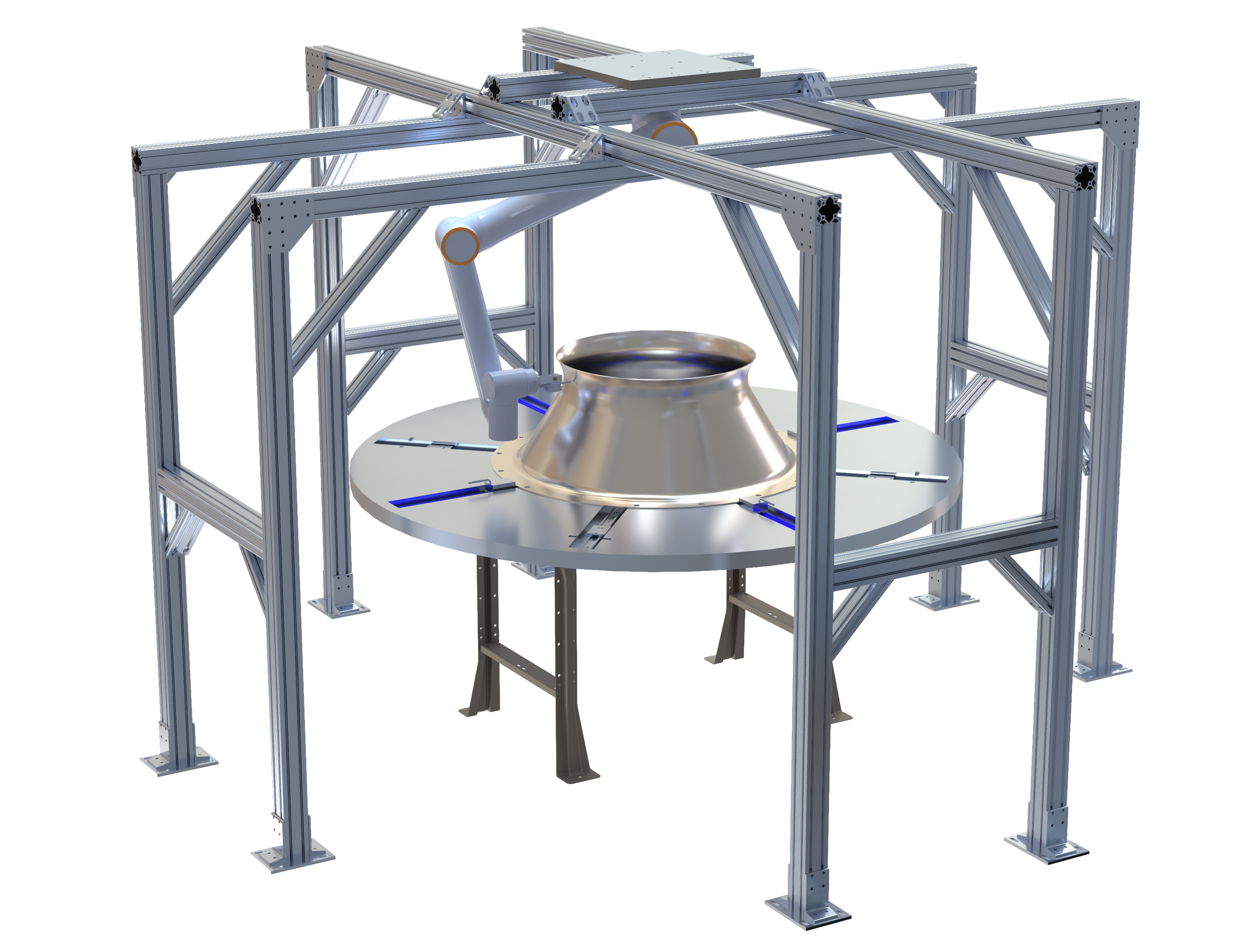
A vertically mounted collaborative robot with an integrated digital dial gauge that standardizes dimensional inspection of industrial fan cones.
±1/16 in
Profile tolerance held
~40
Cone variants supported
0.79 mm
Mount max deflection (FEA)
0.089 mm
Table max deflection (FEA)
$30,000 CAD
Project budget
Overview
An automated inspection cell for Northern Blower Inc. to replace a manual sheet-metal jig that left about 1 in 5 cones flawed. The system holds a ±1/16 in profile tolerance across roughly 40 cone geometries using a Fairino FR10 cobot, a Mitutoyo digital dial gauge, an adjustable 76 in centering table, and a CAD-driven SDK inspection workflow, validated with FEA inside a $30,000 budget.
Problem
Northern Blower Inc. builds custom industrial centrifugal fans. The inlet and fan wheel cones, complex spun-metal geometries supplied by an outside vendor, are inspected on arrival before assembly. The legacy method was a sheet-metal cutout jig checked at about three points per cone, plus a few diameter readings.
That approach was operator-dependent, slow, and unable to detect deviations across the full curved profile. About one in five cones was found flawed, and errors that passed inspection propagated downstream as misalignment, imbalance, vibration, and weld-induced stress, driving rework and scrap.
Objectives & Requirements
Deliver a standardized, repeatable inspection process that holds the ±1/16 in profile tolerance, accommodates all ~40 inlet and fan wheel cone sizes without major reconfiguration, and is operable with minimal training, within a $30,000 CAD budget and the limited floor space of the receiving area.
Client needs were converted into quantifiable target specifications covering diameter range, height range, inspection time, durability cycles, repeatability, and digital compatibility, so the design could be measured against them at every phase.
Concept Selection
Six concepts, from handheld and adjustable-arm 3D scanners to 3D-printed surface checks, were screened against the current jig as a reference datum, then ranked in a weighted decision matrix scoring measurement accuracy, repeatability, part-size adaptability, speed, ease of operation, cost, durability, and safety.
The Vertically Mounted Robotic Arm with an Integrated Digital Dial Gauge ranked first with a weighted score of 4.45, ahead of a handheld 3D scanner, on accuracy, repeatability, and adaptability across the cone range.
Detailed Design
The final cell places each cone on a universal adjustable table; a Fairino FR10 cobot mounted directly overhead carries the dial-gauge end effector and follows a programmed inspection path with full 3D access to the geometry.
Inspection table: a 76 in diameter, 2 in anodized Aluminum 6061-T6 top on powder-coated steel legs. CNC-machined radial grooves carry guide bars, sliding plates, centering blocks, and locking pins. Eight guide bars, four for inlet and four for fan wheel cones spaced 90 degrees apart, re-center any cone size and lock it for repeatable positioning.
Robotic arm mount: 3 in t-slotted Anodized Aluminum 6063-T6 framing forming a plus-shaped main and support structure, topped by a 1 in A36 steel plate that bolts the FR10 base overhead. The modular t-slot design keeps it adjustable and serviceable.
End effector: a CNC-machined aluminum mount, a 2.44 in circular base on the FR10 flange pattern with a rectangular extension that clamps the Mitutoyo digital dial gauge (±0.001 in) in line with the robot Tool Center Point. Aluminum keeps tooling mass low to preserve the arm's dynamic accuracy.
CAD-Driven Programming Workflow
Inspection paths are generated from the nominal CAD models. In SolidWorks, the cone profile is projected, fit to a spline, and sampled with evenly distributed intersection points, then exported as IGES and cleaned in Excel into raw XYZ coordinates, a procedure repeated for every cone size.
The FR10 runs an external SDK (Python/C++) master program rather than separate scripts per cone. The operator selects the cone, the program loads its coordinate file and organizes points into axial layers. For each layer the robot zeroes the gauge, contacts the surface to a 1/16 in compression, sweeps a full 360 degrees, and records deviations wirelessly.
A Workpiece Frame calibration, origin at the table center with a 5.4025 in TCP offset for the end-effector and gauge stack, aligns the robot coordinate system to the physical cone so CAD coordinates map to real-world motion. Each point is graded PASS or FAIL against the ±1/16 in tolerance and logged for traceability.
Engineering Analysis (FEA)
Both structural subsystems were validated in SolidWorks FEA with mesh-convergence studies to confirm the results were mesh-independent before drawing conclusions.
Mount: analysed on a quarter model by symmetry, loaded with the 88 lbf arm weight at a safety factor of 5 and a 2028.3 ft·lbf operating torque at a safety factor of 10, with legs fixed to simulate ground bolting. Maximum deflection was 0.794 mm, below the 1.588 mm (±1/16 in) tolerance, and zeroable on the dial gauge after install.
Table: analysed on a half model under the 250 lb load of the largest inlet cone with a 0.15 in converged mesh. Maximum deflection was 0.089 mm, confirming a stiff inspection platform.
Outcome & Key Learnings
The design meets the functional and accuracy requirements: it holds the ±1/16 in tolerance, supports all ~40 cone variants from a single SDK program, removes operator subjectivity, and adds digital QC traceability, within budget.
The main lesson was systems integration. A working inspection cell required mechanical fixturing, robot programming, and digital metrology to share one calibrated coordinate frame. Tying CAD geometry, FEA validation, and a scalable software workflow together mattered more than optimizing any single part.
Image Gallery
Additional renders, drawings, and analysis outputs from the project.
Supplementary Drawings
Released CAD drawing deliverables produced for this project. The documented deliverables open to a full page with title block, views, and bill of materials; the assembly and part sheets open directly as PDF drawings.
Assembly & Part Sheets
Next project
Unicycle Navigation Controller