Capstone CAD deliverable
Inspection Table Components
Centering and locking hardware that positions inlet and fan wheel cones repeatably on the inspection table.
Part of Automated Cone Inspection System
Aluminium 6061-T6
Material
5
Unique parts
8 (inlet + fan wheel)
Slider bars
Ø0.25 in
Index hole
Overview
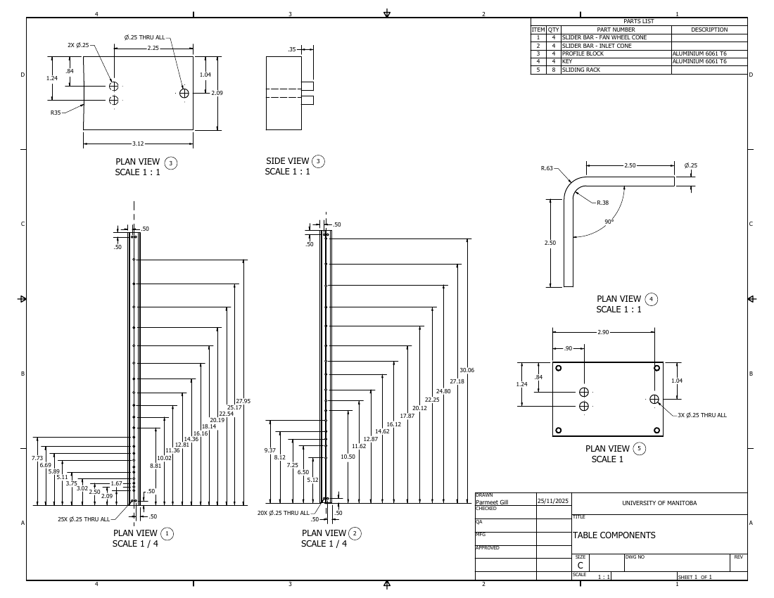
A multi-part detail drawing for the inspection table's centering system: slider bars, profile blocks, keys, and sliding racks that index and lock each cone size on the table.
Bill of Materials
| Item | Qty | Description |
|---|---|---|
| 1 | 4 | Slider bar, fan wheel cone |
| 2 | 4 | Slider bar, inlet cone |
| 3 | 4 | Profile block, Aluminium 6061-T6 |
| 4 | 4 | Key, Aluminium 6061-T6 |
| 5 | 8 | Sliding rack |
Function
These parts make up the centering system on the inspection table. They position both inlet and fan wheel cones on a common datum and lock them so each cone size is measured from the same reference.
Parts & Operation
The parts list covers four fan-wheel slider bars, four inlet slider bars, four profile blocks, four keys, and eight sliding racks. The slider bars carry rows of Ø0.25 in through holes at set positions; these discrete locations index the cone sizes. Profile blocks and keys locate and lock the sliding racks along the bars.
Slider bars use a 1/4 scale plan view to show the full hole pattern; profile blocks, keys, and racks are detailed at 1:1 on a C-size sheet.
Constraints
Hole positions set the cone diameters the table accepts, so their spacing drives the range of sizes supported. Four arms spaced at 90 degrees center the cone, requiring consistent hole positions across paired bars.
Drawing Sheet
The full vector drawing with title block, views, and dimensions. Open in a new tab or download the PDF.
Related Views
Next project
Proximity Probe Bracket (Fabrication)